Login or create an account
CloseReturning Customer
I am a returning customer
Login or create an account
CloseRegister Account
If you already have an account with us, please login at the login form.
Your Account Has Been Created!
Thank you for registering with nanosleds.com!
You will be notified by e-mail once your account has been activated by the store owner.
If you have ANY questions about the operation of this online shop, please contact the store owner.
Account Logout
You have been logged off your account. It is now safe to leave the computer.
Your shopping cart has been saved, the items inside it will be restored whenever you log back into your account.
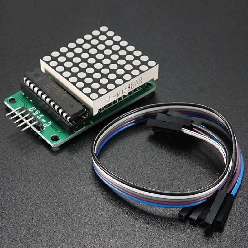
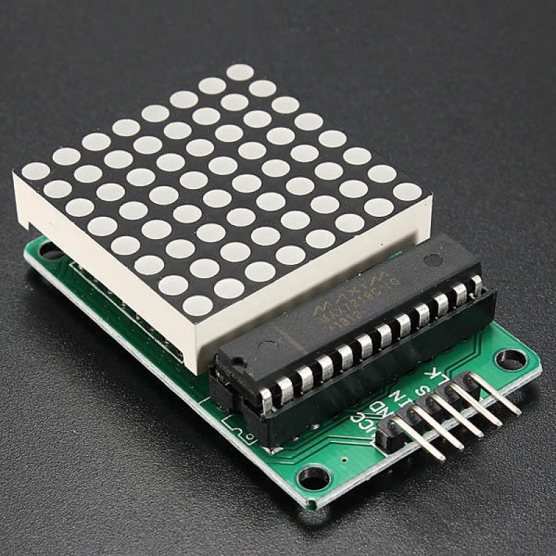
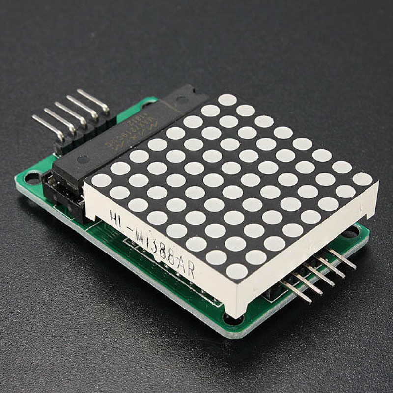
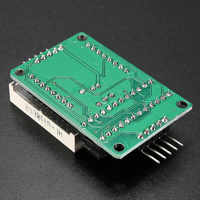
2Pcs MAX7219 Dot Matrix MCU LED Display Control Module Kit
- $5.91
- Ex Tax:$5.91
- Product Code: 2x097972
- Availability: In Stock
2Pcs MAX7219 Dot Matrix MCU LED Display Control Module Kit For Arduino With Dupont Cable Specifications: A single module can drive an 8 x 8 common cathode lattice Operating voltage: 5V Size: 5 x 3.2 x 1.5 cm (L x W x H) LED color: red With four screws hole, aperture 3mm With input and output interfaces, supports multiple modules cascade Wiring in..
2Pcs MAX7219 Dot Matrix MCU LED Display Control Module Kit For Arduino With Dupont Cable
Specifications:
A single module can drive an 8 x 8 common cathode lattice
Operating voltage: 5V
Size: 5 x 3.2 x 1.5 cm (L x W x H)
LED color: red
With four screws hole, aperture 3mm
With input and output interfaces, supports multiple modules cascade
Wiring instructions:
1. The module left side as an input port and the output port on the right
2. To control a single module, just connect the input port to the CPU
3. When cascading multiple modules, the input port of the first module connect to the CPU, the output port connect to the input port of the second one, and so on.
In the case of 51 MCU:
VCC → 5V
GND → GND
DIN → P22
CS → P21
CLK → P20
Note:
1. VCC and GND is not reversed, it would burn the chip!
2. When the 51 microcontroller P0 port controlling, must be connected to the pull-up resistor, it is recommended that the resistance of 4.7K--10K
3. Please install lattice into the round hole first, and then insert the round hole to PCB board and weld. Face the side of lattice with words, from left to right pin order is 123456. PCB board 1st pin is square pad!
4.Electrolytic capacitors long-pin as positive, short-pin as negative; ceramic capacitor hsa no positive and negative points
Package included:
2 x LED module
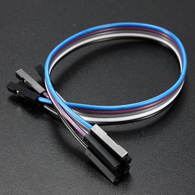
10 x Dupont line (20cm)
